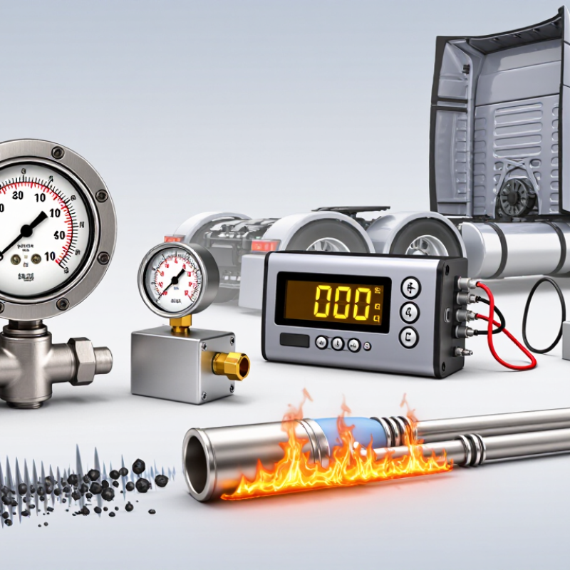
In 2026, global buyers are choosing exhaust instruments for harsher conditions than ordinary pressure measurement. An Exhaust Pressure Gauge may face pulsation, soot, vibration, moisture, and temperatures above 500°C. The correct type depends on the measurement point, pressure range, gas temperature, and installation method.
OICA reported 93.5 million motor vehicles produced worldwide in 2023. Meanwhile, the International Energy Agency reported more than 17 million electric cars sold in 2024. Internal-combustion engines remain widely used in commercial fleets, generators, construction equipment, and industrial burners. This mixed market increases demand for durable backpressure and differential-pressure measurement. However, published market reports rarely isolate exhaust gauges as a separate product category. That gap deserves caution.
The 2026 buyer should compare Bourdon-tube, diaphragm, digital, and remote-sensor designs. A mechanical gauge can provide simple, immediate readings near a turbocharger or diesel filter. A diaphragm model may respond better to low-pressure exhaust restrictions. Digital versions can offer alarms, data logging, and clearer readings inside vibrating engine compartments. Direct mounting is not always wise. A stainless-steel sensing line, cooling coil, or remote transmitter can protect the instrument from thermal shock.
Technical confidence requires more than a large dial. Buyers should verify accuracy, overpressure capacity, temperature limits, connection size, sealing material, and calibration traceability. ISO 17025 calibration records add useful evidence during maintenance audits. EN 837-1 and ASME B40.100 also provide recognized guidance for pressure-gauge performance. Field experience still matters. A gauge that survives laboratory testing may fail after soot enters a narrow impulse line. Careful selection, installation, and periodic inspection remain essential for reliable exhaust-pressure data.
Exhaust pressure gauges measure the resistance that exhaust gas faces before leaving an engine or process system. This pressure is commonly called backpressure. A rising reading may indicate a restricted filter, damaged pipe, or excessive flow. The gauge does not measure gas speed directly. It measures force applied to a sensing element. That distinction matters.
Mechanical gauges often use a Bourdon tube or diaphragm. Pressure bends the element, and a linkage moves the pointer across a scale. Differential gauges compare exhaust pressure with ambient pressure or another reference point. Absolute gauges use a sealed vacuum reference, but they are less common for routine backpressure checks. Select the measurement type carefully. A wrong reference can create a convincing but misleading result.
Installation conditions strongly affect accuracy. Use heat-resistant tubing, keep the sensing port clear, and protect the gauge from vibration. Pulsating exhaust flow can make the pointer jump, so a snubber or dampening device may help. Choose units that match the working range, such as kPa, bar, or psi. Calibration should be checked against a traceable reference at planned intervals. I have found that many “pressure problems” begin with poor hose routing or a blocked port. The gauge may be correct, yet the setup is not. Check the basics again.
2026 Top Exhaust Pressure Gauge Types for Global Buyers
Main Types of Exhaust Pressure Gauges for 2026
Exhaust pressure gauges help technicians monitor backpressure before it affects engine performance or filtration systems. In 2026, buyers commonly choose Bourdon tube, diaphragm, differential, and digital designs. Bourdon tube gauges suit steady readings and rugged workshop environments. Their curved metal tube moves a pointer as pressure changes. They remain practical, but vibration can affect pointer stability over time. This limitation is easy to underestimate.
Diaphragm gauges respond well to lower pressures and contaminated gas paths. A flexible diaphragm separates the sensing mechanism from the exhaust stream. This structure can reduce blockage risks when soot or moisture is present. Differential gauges compare two pressure points, such as before and after a filter. They show pressure loss more clearly than single-point instruments. Correct hose routing matters. A small leak can create a convincing but false reading.
Digital gauges provide clear numbers, peak capture, alarms, and easier data recording. They are useful during road tests and maintenance inspections. However, batteries, heat limits, and electrical noise require careful checking. Mechanical gauges often survive harsh conditions with less setup. Digital models may offer higher resolution, but not always better accuracy. Buyers should verify pressure range, temperature rating, connection size, calibration interval, and response time. No gauge is perfect. Practical testing also shows that oversized ranges can hide small pressure changes.
2026 Top Exhaust Pressure Gauge Types for Global Buyers
Comparing exhaust pressure gauges starts with accuracy, not dial size. ASME B40.100-2022 classifies pressure gauges by performance and testing requirements. A gauge rated at ±1% of full scale can be off by ±0.1 bar on a 0–10 bar range. That error may hide a restricted filter or an overloaded turbocharger. Range comes first. Choose a scale where normal readings sit near the middle, not at the final graduation. NIST pressure-measurement guidance also stresses traceable calibration and uncertainty evaluation. A certificate without stated uncertainty is incomplete, in my view.
Durability depends on the exhaust environment. Pulsation, soot, vibration, and rapid temperature changes can damage a sensitive mechanism. A glycerin-filled gauge may reduce pointer vibration, while a stainless enclosure offers better resistance in wet engine compartments. Yet filling is not a cure-all. Poor mounting can still distort readings. Check the specified media temperature, ambient temperature, overpressure limit, and ingress rating. ISO/IEC 17025 calibration records add credibility when buyers compare suppliers across regions.
Digital gauges provide easier logging and alarm settings, but batteries and sensors introduce new failure points. Mechanical gauges are simpler, though parallax can affect readings. I would compare repeatability during three cold-to-hot cycles, not only the catalog accuracy. That test takes time. It also reveals weaknesses that polished datasheets often miss.
2026 Top Exhaust Pressure Gauge Types for Global Buyers
Choosing an exhaust pressure gauge starts with the system, not the dial. Diesel engines often need a rugged Bourdon-tube gauge for steady backpressure monitoring. Turbocharged engines may require a gauge with a wider range and vibration resistance. Gas engines can create stronger pulsations, so a damped mechanical gauge or digital gauge with filtering may provide clearer readings.
Industrial systems demand closer attention to temperature and contamination. Furnaces, boilers, and process ducts may need remote-mounted gauges connected through impulse tubing. A diaphragm seal can protect the sensing element from corrosive gases, soot, or sticky deposits. Keep the gauge away from direct exhaust heat when possible. Heat damages accuracy quietly.
Select a pressure range that places normal readings near the middle of the scale. A range about 1.5 to 2 times working pressure is commonly practical, but the system manual should control the final choice. Check pressure units, connection size, thread standards, accuracy class, and calibration records. Vibration, condensation, and pressure spikes are easy to underestimate. They are not minor details. Field experience shows that a perfect gauge can still fail when installed without a snubber or cooling loop. Recheck readings against a certified reference during maintenance. Some systems behave differently under load, and that deserves honest review.
The chart compares representative full-scale pressure ranges commonly selected for different engines and industrial systems. Low-pressure manometers and diaphragm gauges suit draft and backpressure monitoring, while digital differential, Bourdon tube, and remote-sensing gauges cover higher-pressure or high-temperature applications. Actual selection should be verified against the equipment design, temperature, vibration, and OEM pressure limits.
For global buyers, exhaust pressure gauge selection starts with standards, not appearance. Bourdon-tube gauges suit stable, medium-to-high pressure systems. Diaphragm gauges perform better with low pressure or contaminated exhaust. Digital gauges offer clearer readings, but batteries and electronics need protection. ASME B40.100 defines pressure-gauge performance requirements, while EN 837-1 supports European mechanical gauge specifications. Confirm the required standard before comparing prices.
Installation conditions often decide accuracy. Mount the gauge where vibration is limited and the dial remains visible. Use a snubber for pulsating exhaust pressure. A suitable connection thread prevents leakage and reduces adapter errors. The U.S. Department of Energy reports that compressed air can consume about 10% of industrial electricity. Small pressure losses can therefore create measurable operating costs. This figure is broad, but it deserves attention.
Tips: Check range, accuracy class, connection size, and temperature limits. Keep normal pressure near the middle of the scale. Inspect zero drift during planned maintenance. Replace damaged lenses immediately. In my view, buyers sometimes overvalue digital displays and undervalue installation space. That is an imperfect judgment. A simple mechanical gauge may remain more practical in hot, dusty environments. Record readings monthly and compare them with equipment limits. Maintenance teams should also review calibration intervals against site risk, not only supplier recommendations.
| Gauge Type | Typical Measuring Range | Best-Fit Exhaust Application | Accuracy and Display | Common Connection and Materials | Key Standards or Requirements | Installation Priorities | Maintenance and Service Interval | Global Buying Considerations |
|---|---|---|---|---|---|---|---|---|
| Positive Pressure Gauge | Approximately 0–1 bar to 0–25 bar, depending on the exhaust system | Engine exhaust back pressure, industrial ducts, combustion equipment, and process gas lines operating above atmospheric pressure | Commonly Class 1.0, 1.6, or 2.5; analog pointer or digital LCD display | Usually radial or rear threaded connection; stainless steel or copper-alloy wetted parts; typical threads include G, NPT, or metric forms | Select a gauge designed and tested in accordance with applicable pressure-gauge requirements such as EN 837-1 or ASME B40.100; verify local pressure-equipment rules | Install at a representative pressure point, avoid excessive vibration, use a suitable seal, and confirm that the connection thread matches the system | Inspect for pointer drift, blocked ports, leakage, and case damage; calibrate at least annually or according to the site quality program | Confirm pressure unit, thread standard, temperature rating, corrosion resistance, and required documentation before import or installation |
| Compound Pressure and Vacuum Gauge | Typical scales range from -1 bar vacuum to 0.6, 1.5, 2.5, or 4 bar positive pressure | Exhaust systems that may experience both suction and positive back pressure, including fans, extractors, and air-handling equipment | Usually Class 1.6 or 2.5; dual-scale dials may show bar and psi or kPa | Threaded process connection; brass or stainless steel pressure components; optional liquid-filled case for vibration reduction | Use a pressure range that covers both the vacuum and positive-pressure conditions; select units and dial markings suitable for the destination market | Install with the zero point visible, keep the pressure port free of condensate and soot, and avoid exceeding either scale limit | Check zero return and both scale directions during routine inspections; clean the sensing path and recalibrate after overload or abnormal readings | Useful for multi-market equipment, but buyers should verify whether the selected scale and unit system are accepted by local operators and inspectors |
| Differential Pressure Gauge | Commonly 0–25 Pa, 0–250 Pa, 0–2.5 kPa, or higher for duct and filter applications | Filter blockage monitoring, scrubber systems, ventilation ducts, exhaust fans, and pressure loss across silencers or heat exchangers | Typically 1.5–2.5% of full scale for mechanical models; digital models may offer configurable units and alarm outputs | Two pressure ports marked high and low; tubing connections are common; diaphragm or capsule sensing elements are selected according to pressure and media | For safety-related or regulated equipment, verify applicable ventilation, emissions, electrical, and measurement requirements in the destination country | Connect high and low ports correctly, route impulse tubing without sharp bends, and protect low-range instruments from condensation and dust | Check both ports for blockage, compare the zero reading with the system at equal pressure, and test alarm thresholds during scheduled service | Specify differential range rather than only line pressure; confirm tubing size, alarm functions, enclosure rating, and replacement availability |
| High-Temperature Exhaust Gauge | Often 0–1 bar, 0–2 bar, or 0–5 bar with a remote sensing point | Diesel and gas engine exhaust, kilns, furnaces, incineration systems, and high-temperature process exhaust | Accuracy depends on the gauge and cooling arrangement; a remote diaphragm seal, impulse line, or cooling coil is commonly required | Stainless steel pressure parts are preferred for corrosive or hot gases; connection materials must tolerate the measured temperature | Verify maximum process temperature, ambient temperature, pressure rating, materials compatibility, and any applicable exhaust-emission equipment requirements | Do not expose a standard gauge directly to gas above its rated temperature; use a cooling element, sufficient impulse-line length, and thermal shielding where necessary | Inspect for heat discoloration, hardened seals, blocked impulse lines, and thermal fatigue; recalibrate after overtemperature exposure | Temperature rating is often more important than nominal pressure range; request temperature derating data and material certificates for demanding service |
| Liquid-Filled Pressure Gauge | Commonly 0–1 bar to 0–25 bar; range should place normal operation near the middle of the dial | Vibration-heavy engines, mobile equipment, compressors, pumps, and exhaust systems with mechanical pulsation | Often Class 1.0 or 1.6; filling liquid dampens pointer movement and improves readability under vibration | Stainless steel case and process components are common; fill liquid must be compatible with the operating temperature and environment | Check enclosure and ingress-protection requirements, temperature limits of the fill liquid, and pressure-gauge conformity documentation | Mount upright where possible, use a snubber or restrictor for severe pulsation, and leave any manufacturer-provided vent in the correct position | Look for fill discoloration, leakage, condensation, and pointer instability; replace damaged gauges rather than refilling them in the field unless designed for service | Confirm low-temperature performance, shipping orientation, case sealing, and whether the fill liquid is acceptable for the installation environment |
| Digital Exhaust Pressure Gauge | Ranges may extend from low differential pressure to several hundred bar, depending on the sensor design | Remote monitoring, data logging, engine diagnostics, filter condition monitoring, and systems requiring switch or transmitter outputs | Typical stated accuracy is approximately 0.25–1.0% of full scale; display units may include Pa, kPa, bar, psi, or inH₂O | Electrical output may include switch, analog, or digital communication; choose sensor materials and seals compatible with the exhaust medium | For powered equipment, verify applicable EMC, electrical safety, ingress-protection, hazardous-area, and national conformity requirements | Provide correct power supply, cable protection, grounding, strain relief, and signal isolation; locate the sensor away from direct exhaust heat unless rated for it | Check battery or power status, compare readings with a calibrated reference, inspect wiring, and verify alarm set points at planned intervals | Evaluate software, connector type, IP rating, language requirements, cybersecurity needs, spare sensors, and long-term availability of replacement batteries |
| Panel-Mount Exhaust Gauge | Selected according to the equipment design, commonly 0–1 bar, 0–2 bar, or 0–10 bar | Control cabinets, engine instrument panels, generator sets, boiler panels, and operator stations | Analog versions commonly use 63–100 mm dial sizes; digital versions provide numerical display and optional alarm indication | Rear connection or remote pressure line; front bezel and case should match the panel cutout and required enclosure protection | Verify panel cutout, enclosure rating, vibration resistance, electrical conformity, and measurement accuracy requirements | Use a secure panel gasket, support long impulse lines, prevent line vibration, and ensure the dial remains readable from the operator position | Inspect bezel, lens, mounting hardware, and connections; test the indicated pressure against a reference gauge during planned shutdowns | Confirm cutout dimensions, viewing angle, unit markings, spare-panel compatibility, and availability of local service or replacement parts |
| Remote-Mount Gauge with Impulse Line | Commonly 0–1 bar to 0–25 bar, with the range matched to the expected exhaust back pressure | Hot, inaccessible, vibrating, or hazardous exhaust points where the display must be installed away from the process connection | Accuracy depends on the gauge and the impulse-line installation; response time may be slower than direct mounting | Small-bore stainless steel or high-temperature tubing with compression fittings is common; isolation valves and test points are recommended | Pressure tubing, fittings, isolation valves, and gauge must all meet the applicable pressure, temperature, and material requirements | Route tubing continuously where possible, avoid low points that collect condensate, protect it from mechanical damage, and provide adequate support | Drain or clean the impulse line when permitted, check fittings for leaks, confirm response time, and calibrate the gauge with the line included in the test setup | Review tube dimensions, fitting standards, spare tubing availability, export packaging, and installation practices used in the destination region |

© 1999-2025 The Lincoln Electric Company