
How to Choose a Robotic Welding System in 2026?

Choosing a robotic welding system in 2026 requires more than comparing robot speed, payload, or advertised accuracy. A reliable decision begins on the shop floor, beside the fixture, wire feeder, and fume extraction system. The best solution must match actual weld lengths, material thicknesses, joint access, production volume, and operator skills. A system that performs beautifully in a demonstration may struggle with distorted parts or inconsistent fit-up.

This guide examines robotic welding through practical experience, engineering judgment, and verifiable evidence. It considers robot reach, torch positioning, power-source compatibility, seam tracking, offline programming, safety functions, and maintenance support. Current ISO 10218 requirements and local workplace rules should be checked before purchase. Documentation matters. So does the integrator’s field record. Ask for measured cycle times, sample weld results, training plans, spare-parts availability, and service response commitments. Numbers alone can mislead.

Small details often decide the outcome. A poorly placed cable can rub against a sharp fixture edge. A five-second tool change can become hours of lost production each week. Good equipment cannot fully correct weak fixturing or unstable welding parameters. That point is easy to underestimate. Cost calculations should include installation, programming, consumables, downtime, guarding, and future upgrades. The newest technology may not be the wisest choice. A simpler cell, properly configured and supported, can deliver better long-term value. This article provides a careful framework for comparing options and recognizing where assumptions still need testing.
How to Choose a Robotic Welding System in 2026?

Define Production Needs: Batch Size, Weld Length, Takt Time, and Part Mix

A robotic welding system should match your production reality, not an idealized catalog example. Start with batch size. A cell producing 400 identical frames can justify fixed fixtures and dedicated programming. A cell producing 40 varied assemblies needs faster changeovers. Record actual weekly volumes, not optimistic forecasts.

Measure weld length on each part. A 1.5-meter seam demands different torch travel than six short brackets. Then calculate takt time from available minutes and required output. Include loading, clamping, repositioning, inspection, and wire changes. A robot that welds quickly may still miss takt time when operators wait for fixtures. Leave practical capacity margin. Production rarely runs perfectly.

Part mix is often the difficult variable. List every part family, joint type, material thickness, and weld position. Note how frequently operators change fixtures or programs. In one shop-floor assessment, a mixed batch caused more lost time during setup than welding. Our first estimate ignored fixture cleaning, so the planned cycle looked reliable but failed during longer shifts. That mistake changed the evaluation.

Test representative parts before selecting equipment. Use the heaviest assembly, the longest weld, and the most awkward access point. Check reach, torch angles, cable movement, and operator loading effort. Ask for measured cycle data, not only simulation results. Keep a simple production log for two weeks. It may reveal that part mix, rather than robot speed, controls output.

Calculate Capacity: Target 40–60% Arc-On Time and Required Robot Utilization

How to Choose a Robotic Welding System in 2026?

Calculate Capacity: Target 40–60% Arc-On Time and Required Robot Utilization

Capacity should begin with arc-on time, not robot speed. Arc-on time measures when the welding arc is actually active. For many production cells, a practical planning target is 40–60% of scheduled time. Below 40%, the robot may wait too often. Above 60%, maintenance, loading, inspection, and changeovers can become dangerously compressed. A 2024 International Federation of Robotics report recorded more than 541,000 industrial robot installations worldwide in 2023. That growth makes capacity discipline more important, not less.

Use a simple calculation. If one shift provides 420 available minutes, a 50% arc-on target equals 210 welding minutes. A part requiring 32 arc-on seconds needs about 394 parts per shift before losses. Add fixtures, wire changes, operator loading, rework, and planned downtime. The required robot utilization then becomes required productive minutes divided by scheduled available minutes. For example, 300 productive minutes from 420 available minutes requires 71.4% utilization. That may be achievable, but it leaves little recovery time.

The first estimate is rarely right. A neat spreadsheet can still lie. Record real cycle times for several weeks, including pauses and rejected welds. The Manufacturing Institute and Deloitte projected major manufacturing labor shortages through 2033, increasing pressure to automate carefully. Choose a system that meets demand near the middle of its operating range, rather than one that survives only perfect shifts.

Match Robot Specifications: Six Axes, Reach, Payload, and ±0.1 mm Repeatability

How to Choose a Robotic Welding System in 2026?

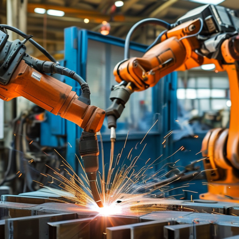
A six-axis robot offers flexible torch movement around frames, brackets, and curved joints. This flexibility matters when fixtures cannot expose every weld angle. In production trials, I check whether the wrist can rotate without twisting cables or colliding with clamps. More axes do not automatically mean better weld quality. Poor programming can still create uneven travel speed.

Reach must cover the complete work envelope, not just the largest part dimension. Leave clearance for the torch, dress pack, fixtures, and operator access. A robot with barely sufficient reach may work on paper, then fail near the rear corner. Measure actual joint locations. Do not rely only on catalog diagrams.

Payload includes the torch, mounting plate, cables, sensors, and any cleaning equipment. A six-kilogram torch package can exceed a robot’s comfortable capacity after accessories are added. Confirm wrist load, inertia, and center-of-gravity limits. The ±0.1 mm repeatability figure also needs careful reading. It usually describes repeated positioning under defined test conditions, not guaranteed weld accuracy. Heat, fixture movement, wire variation, and poor calibration can reduce results. I have seen precise robots produce inconsistent beads because the fixture was slightly distorted. That lesson is easy to miss. Test representative joints with real materials, wire, and welding positions before approval. Keep the test records.

How to Choose a Robotic Welding System in 2026?

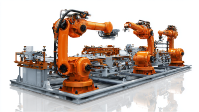
Typical engineering benchmarks for six-axis robotic welding systems. Reach, payload, and repeatability should be matched to the workpiece size, torch package, fixture access, and weld path accuracy.

Common selection ranges: approximately 1.4–2.6 m reach, 6–30 kg payload, and ±0.05–±0.15 mm repeatability. Six-axis kinematics provide the orientation flexibility needed for multi-position welding.

Select Welding Equipment: MIG/MAG, TIG, Wire Diameter, Positioners, and Sensors

How to Choose a Robotic Welding System in 2026?

Choosing a robotic welding system begins with the joint, material, and production rhythm. MIG or MAG usually suits repeated steel fabrication and higher deposition rates. TIG offers cleaner, controlled welds, but it often requires slower travel and stricter surface preparation. Test both processes on real samples, not polished demonstrations. I have seen a fast setup fail when small gaps changed during assembly.

Wire diameter also matters. A thicker wire can increase deposition, yet it may reduce control on thin sections. Match the wire to plate thickness, current range, and expected heat input. Positioners should hold the workpiece firmly while allowing smooth rotation. Check load capacity, repeatability, and access to difficult angles. Poor positioning can force the robot into awkward wrist movements.

Tips: Record weld current, voltage, travel speed, and shielding-gas flow during trials. Inspect penetration and distortion after cooling. Add sensors when part variation is unavoidable. Seam tracking can correct joint shifts, while touch sensing helps locate inconsistent starts. Keep sensor signals stable and protected from spatter. Do not assume more automation means better welding. Sometimes, a simpler fixture performs more reliably. Review failed welds with operators before changing the system. Their practical observations may expose problems that software data misses.

Validate Integration: ISO 10218, ISO/TS 15066, Training, Maintenance, and ROI

How to Choose a Robotic Welding System in 2026?

A suitable robotic welding system must fit your entire production environment. In commissioning reviews, I examine workflow, access, fixturing, operator movement, and material variation. Compliance should begin before installation, not after an incident. ISO 10218 provides key safety requirements for industrial robot systems. ISO/TS 15066 supports risk assessment for collaborative robot applications. However, neither document replaces local regulations or a task-specific safety study. Welding heat, fumes, sparks, and awkward workpieces may still require guarding, extraction, interlocks, and controlled access. Ask the integrator for risk assessments, validation records, electrical drawings, and clear responsibility boundaries.

Tips: Request a live cycle demonstration using your actual parts. Check weld consistency after repeated starts and stops. Confirm training covers programming, safe recovery, inspection, and fault diagnosis. Do not accept a polished demonstration as proof of production readiness.

Training and maintenance strongly affect long-term performance. Operators need practical instruction, not only classroom certificates. Maintenance staff should understand torch alignment, cable wear, sensor checks, and scheduled calibration. Keep spare consumables and define response times before signing the contract. A clear maintenance log can reveal recurring faults early. It also supports audit readiness. ROI calculations should include integration, fixtures, extraction, training, downtime, energy, consumables, and safety upgrades. A spreadsheet may promise fast payback. Our early estimate was too optimistic when changeover delays were ignored. Recalculate using real shift data, reject rates, and conservative uptime assumptions. Profitability must survive ordinary production problems.