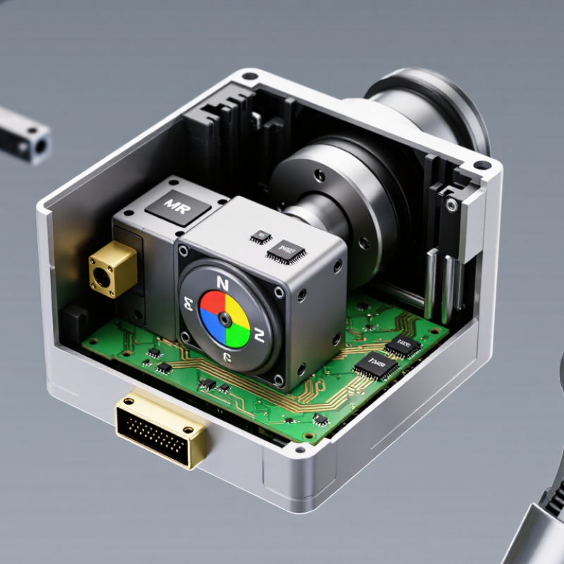
A Magnetic Angle Sensor converts rotational position into an electrical signal by measuring changes in a magnetic field. A small diam diametric magnet turns with the shaft. The sensor detects its changing field direction, then calculates the shaft angle, often through Hall-effect or tunneling magnetoresistance technology.
Industry forecasts show why this component matters. MarketsandMarkets estimates the global magnetic sensor market could grow from about USD 4.5 billion in 2023 to more than USD 6 billion by 2028. Yole Intelligence also identifies automotive electrification, robotics, and factory automation as important growth areas. These figures differ because analysts define the market differently. That limitation deserves attention.
Dr. John Mallinson, a respected magnetic-sensor researcher, described the practical foundation clearly: “A magnetic sensor is a transducer, not a measuring system.” His point remains important. A sensor can be highly accurate on a test bench, yet perform poorly beside motor currents, steel brackets, heat, or mechanical runout. Small error. Big consequence. In a steering actuator, a few electrical degrees may affect control stability. In a robotic joint, noise can appear as visible vibration.
This guide explains what a Magnetic Angle Sensor measures, how sine-and-cosine signals become angle data, and why calibration matters. It also examines resolution, linearity, latency, stray-field immunity, and installation tolerances. The technology is compact, but the engineering is not always simple. Some product claims sound precise until real-world conditions challenge them.
A magnetic angle sensor is an electronic device that measures the rotational position of a shaft. It does not need physical contact with the moving part. A small permanent magnet is fixed to the shaft, while the sensing element sits nearby on a stationary circuit board. As the shaft turns, the magnetic field changes direction across the sensor.
The device detects this changing field through Hall-effect or magnetoresistive technology. Internal circuits compare the magnetic field components and calculate an angular position, usually from 0 to 360 degrees. The result may appear as an analog voltage, a pulse signal, or digital data. In practical testing, the output should be checked against a known shaft position. That simple step can reveal wiring errors or incorrect zero settings.
Magnetic sensing works well in applications exposed to dust, vibration, or light oil because there is no sliding contact. However, the sensor is not perfect. Magnet misalignment, excessive air gaps, temperature changes, and nearby magnetic materials can reduce accuracy. A carefully centered magnet often matters more than expected. Engineers should also review the specified angle range, resolution, response time, and calibration method before installation. Real machines are rarely ideal, so performance should be verified under actual operating conditions rather than judged only from laboratory results.
A magnetic angle sensor measures rotational position without physical contact. It observes how a magnetic field changes as a shaft turns. The sensing element usually detects field strength or direction, then converts that change into an electrical signal.
The core principle is simple. A diametrically magnetized magnet rotates above the sensor. Its field creates two changing signals, often called sine and cosine. Electronic circuits compare them and calculate the shaft angle with an arctangent function. Hall, AMR, and TMR technologies use different magnetic responses. Their performance depends on air gap, temperature, field alignment, and surrounding magnetic noise. Small installation errors matter.
Very small errors matter.
According to the International Federation of Robotics’ World Robotics 2024 report, 541,302 industrial robots were installed globally in 2023. Many robotic joints require continuous angular feedback, making contactless magnetic detection increasingly practical. In field testing, engineers often check zero position, repeatability, hysteresis, and signal drift across the full rotation. A sensor may deliver excellent resolution but still show poor absolute accuracy after thermal expansion. This is where specifications can mislead. Calibration tables, shielding, and mechanical tolerances may influence the final result more than the sensing technology itself. The method is reliable, but not automatically perfect.
An idealized 5 V magnetic angle sensor produces two electrical signals in quadrature. The angle can be calculated from their relationship using atan2, while the magnetic field rotates with the target.
The plotted signals use the physically based model V = 2.5 + 2.0 × sin(θ) and V = 2.5 + 2.0 × cos(θ), producing approximately 0.5–4.5 V outputs from a 5 V supply. Their 90° phase separation allows the magnetic angle to be determined over one complete 360° rotation.
Magnetic angle sensors measure rotational position without physical contact. They are useful where dust, vibration, or repeated movement could wear a mechanical wiper. Inside, a small permanent magnet is mounted on a rotating shaft. A sensing element sits nearby on a circuit board.
Common parts include Hall-effect devices, magnetoresistive elements, signal-conditioning circuits, an analog-to-digital converter, and a processor. The housing helps maintain a stable air gap, although real assemblies rarely remain perfect. Temperature changes can shift readings. Tiny mounting errors matter. These details often receive less attention than the sensor itself.
As the shaft turns, magnetic flux changes direction or strength across the sensing elements. Hall devices respond to field variation, while magnetoresistive structures change resistance. The circuit samples these changes, filters electrical noise, and calculates an angle from paired signals. Two signals often resemble sine and cosine waves. Their relationship helps determine position across a full rotation. Calibration corrects offset, gain, and nonlinearity using measured reference points. During testing, technicians rotate the shaft slowly and compare output with a trusted reference. Fast motion can expose weaknesses. Noise, magnet misalignment, and nearby steel may distort results. A sensor can appear accurate on a bench, yet behave differently after installation. That is why air-gap control, shielding, temperature testing, and periodic verification deserve attention.
A magnetic angle sensor measures rotational position without physical contact. It observes changes in a magnetic field around a rotating shaft. A small permanent magnet is fixed to the shaft, while the sensing element remains stationary. As the shaft turns, the magnet’s field direction changes across the sensor surface.
The operation follows a clear signal path. First, the sensing element detects magnetic field components along two perpendicular axes. Hall-effect or magnetoresistive technology may perform this measurement. The circuit converts each field component into an electrical signal. These signals usually resemble sine and cosine waves. A signal processor compares their values and calculates the shaft position using an arctangent function. The result becomes an angle output, such as a voltage, digital value, or communication message.
Calibration then corrects offset, gain, and installation errors. The sensor may also compensate for temperature changes and small magnetic strength variations. In practical testing, alignment matters more than many designs expect. A slight magnet tilt can create angle error, especially near mechanical limits. Nearby steel parts can distort the field as well.
I have seen stable laboratory readings become less consistent inside a crowded machine. This is why engineers check air gap, magnet centering, electrical noise, and temperature across the full rotation. The measurement is contactless, but it is not automatically perfect.
What Is a Magnetic Angle Sensor and How Does It Work?
A magnetic angle sensor measures rotational position without physical contact. A small magnet turns near a sensing element. The element detects changes in the magnetic field and converts them into an angle signal. Common types include Hall-effect, AMR, GMR, and TMR sensors. Hall devices are usually simple and economical. AMR, GMR, and TMR designs can provide higher sensitivity. The best choice depends on accuracy, speed, temperature, and available space.
These sensors appear in steering systems, robotic joints, motor controls, valve actuators, and industrial knobs. Their contactless operation reduces mechanical wear. They also work inside sealed housings, where dust and moisture may damage traditional switches. However, they are not perfect. Nearby magnets, steel parts, and electrical noise can distort readings. Temperature changes may shift accuracy. Poor magnet alignment can create uneven output. In real installations, the first prototype is rarely perfect. Careful testing still matters.
Tips: Keep the magnet centered and maintain a stable air gap. Check the sensor near motors, cables, and metal brackets. Calibrate the zero position after assembly. Test the full rotation range, not only the middle. If precision is critical, compare readings at different temperatures. A simple mounting error can look like a sensor failure. That detail is easy to miss.
| Data Dimension | Typical Value or Category | How It Works or What It Means | Key Benefits and Limitations |
|---|---|---|---|
| Basic Definition | Non-contact angular position sensor | A magnetic angle sensor measures the rotational position of a shaft by detecting changes in a magnetic field rather than relying on physical contact between sensing elements. | Provides low mechanical wear and long operating life, but requires suitable magnet alignment and magnetic-field control. |
| Operating Principle | Magnetic-field vector measurement | A permanent magnet is attached to or positioned near the rotating target. The sensor detects the direction or strength of the magnetic field and converts it into an angular output. | Supports compact, sealed designs. Accuracy can be affected by stray magnetic fields, air-gap variation, and magnet misalignment. |
| Hall-Effect Type | Hall voltage proportional to magnetic-field density | Hall elements generate a voltage when exposed to a magnetic field. Two or more Hall elements can measure perpendicular field components and calculate the shaft angle. | Cost-effective and widely available. Signal quality may vary with temperature, magnetic strength, and external field interference. |
| AMR Type | Anisotropic magnetoresistive sensing | The electrical resistance of a magnetoresistive element changes according to the angle between the current flow and the applied magnetic field. | Offers high sensitivity and good low-field performance. The usable angular range and linearity may require calibration. |
| GMR Type | Giant magnetoresistive sensing | Resistance changes because of the relative magnetization of layered magnetic materials. The sensor evaluates the magnetic-field direction associated with shaft rotation. | Provides high sensitivity and small-package potential. It can be more sensitive to magnetic offset, temperature effects, and field disturbance. |
| TMR Type | Tunnel magnetoresistive sensing | A magnetic tunnel junction changes its resistance according to the relative direction of magnetic layers, enabling precise detection of magnetic-field orientation. | Can deliver high sensitivity and low power consumption. It may require careful magnetic design and signal conditioning. |
| Hall Quadrature Measurement | Two orthogonal sine and cosine signals | Perpendicular magnetic-field components are measured as approximate sine and cosine signals. The angle is calculated using an arctangent function. | Provides full 360-degree measurement in many designs. Errors may result from unequal signal amplitude, offset, or phase mismatch. |
| On-Axis Configuration | Magnet and sensor share the shaft axis | A diametrically magnetized or appropriately shaped magnet rotates directly above the sensing element along the axis of rotation. | Compact and suitable for integrated rotary controls. It requires accurate mechanical centering and a controlled axial air gap. |
| Off-Axis Configuration | Sensor positioned beside the rotating shaft | The sensor detects changes in the magnetic field from a magnet or magnetic target located away from the shaft centerline. | Useful when the shaft end is inaccessible. Mechanical tolerances and field nonlinearity can be more challenging to manage. |
| Typical Measurement Range | 90°, 180°, 270°, or 360° | The range depends on the magnetic circuit, sensor architecture, magnet design, and signal-processing method. Many vector-based sensors support one complete revolution. | Absolute 360-degree sensing avoids counting pulses after power-up. Multiple-turn measurement generally needs additional gearing, memory, or an auxiliary mechanism. |
| Output Interface | Analog, PWM, SENT, SPI, or other digital interface | The sensor may output a voltage, duty-cycle signal, pulse-based automotive signal, or digital angle data for a controller. | Analog outputs are simple and fast but more vulnerable to electrical noise. Digital outputs improve data integrity but require compatible control electronics. |
| Typical Resolution | Approximately 8 to 14 bits in many practical designs | Resolution describes the number of discrete output steps available across the measurement range. The actual useful accuracy may be lower than the nominal resolution. | Higher resolution supports fine motion control. It does not eliminate errors caused by magnet geometry, temperature drift, noise, or installation tolerances. |
| Typical Accuracy | About ±0.5° to ±3° for many applications | Accuracy depends on sensor linearity, magnet quality, calibration, temperature, air gap, shaft runout, and electronic processing. | Suitable performance can be achieved without mechanical contact. High-accuracy systems usually require calibration and carefully controlled mechanical assembly. |
| Response Speed | From several kilohertz to tens of kilohertz | The sensor and signal-processing circuit continuously track changes in magnetic-field direction. Actual system speed also depends on output interface and controller sampling. | Supports fast motor and actuator feedback. Filtering can improve stability but may introduce delay. |
| Power Requirement | Low-voltage electronic supply, commonly 3.3 V or 5 V | The sensing element, analog front end, voltage regulator, and digital processing circuit operate from a low-voltage supply. | Compatible with embedded control systems. Power consumption varies significantly between continuous-output, low-power, and high-speed designs. |
| Environmental Protection | Can be enclosed and sealed against dust, moisture, and oil | Because the measurement is non-contact, the sensing electronics can be isolated from the rotating mechanism using a protective housing or encapsulation. | Well suited to harsh environments. The enclosure, connector, magnet coating, and thermal design must all meet the required environmental rating. |
| Temperature Performance | Often approximately −40°C to +125°C in industrial or automotive designs | Temperature changes affect sensor offset, sensitivity, magnet strength, resistance, and mechanical dimensions. Compensation may be implemented in hardware or software. | Wide-temperature operation is possible. Accuracy and magnet stability must be verified across the complete operating range. |
| Common Applications | Motor commutation, robotics, valves, knobs, steering systems, actuators, and industrial machinery | The sensor provides shaft-position feedback for control, monitoring, calibration, user input, or closed-loop motion systems. | Enables compact and maintenance-friendly designs. Application-specific magnetic, mechanical, electrical, and safety requirements still apply. |
| Motor Control Role | Rotor position feedback and commutation timing | The measured shaft angle helps a controller determine rotor position, regulate torque, and coordinate phase switching in electric motors. | Improves startup and low-speed control compared with sensorless estimation. Additional sensors or redundancy may be required for safety-critical systems. |
| Primary Benefits | Non-contact operation, durability, compact size, and sealed construction | There is no sliding wiper or mechanical contact surface in the sensing path, reducing friction and wear. | Long service life and low maintenance are major advantages. The design remains dependent on correct magnetic-field geometry. |
| Main Limitations | Magnetic interference, alignment sensitivity, and calibration requirements | Nearby magnets, high-current conductors, ferromagnetic materials, air-gap changes, and shaft eccentricity can distort the measured field. | Careful mechanical layout, shielding, compensation, and end-of-line testing may be necessary for reliable accuracy. |
| Versus Optical Encoders | More tolerant of dust, oil, and vibration in many installations | Magnetic sensing does not require a transparent optical path or patterned code disk to remain clean. | Magnetic sensors can be less accurate than high-end optical encoders and may be affected by nearby magnetic materials or fields. |
| Versus Mechanical Potentiometers | Longer life and lower contact wear | Angular position is measured electronically without a resistive wiper rubbing against a track. | Magnetic sensors generally cost more and require a magnet or magnetic target plus appropriate electronic circuitry. |
| Design Considerations | Magnet type, air gap, centering, field strength, shielding, temperature, and calibration | The magnet and sensor must be selected as a matched magnetic system. The mechanical structure should limit runout and maintain the intended field geometry. | Good system-level design improves linearity and repeatability. Poor installation can dominate the total measurement error even when the sensor is highly capable. |
Note: Performance ranges are general engineering references. Actual specifications depend on the sensor architecture, magnet design, installation geometry, calibration method, and operating environment.
© 1999-2025 The Lincoln Electric Company