
Robotic TIG welding is moving from specialist fabrication cells into more flexible production environments. Global buyers now expect cleaner beads, repeatable heat input, and measurable productivity. The International Federation of Robotics reported 541,302 industrial robots installed worldwide in 2023, with more than four million operating globally. That figure does not isolate TIG systems, but it shows the expanding automation base supporting robotic welding investment.
The 2025 Top Robotic TIG Welding Machines for Global Buyers guide examines machines through practical buying criteria. These include arc stability, wire-feeding accuracy, torch cooling, positioner synchronization, seam tracking, programming access, and service support. A machine may produce an attractive test weld yet struggle with thin stainless steel, changing joint gaps, or long production shifts. Real workshops reveal these weaknesses quickly. Ask for sample welds.
Industry expectations also extend beyond welding speed. ISO 10218 addresses industrial robot safety, while IEC 60204-1 covers electrical equipment for machinery. Buyers should verify documentation, guarding, emergency-stop design, operator training, and local conformity requirements before ordering. The American Welding Society continues to emphasize procedure control, welder qualification, inspection, and proper parameter management in welding operations.
Reported market values differ widely because research firms define robotic welding differently. Some include complete cells, while others count robots or welding power sources alone. That inconsistency deserves attention. This guide therefore avoids treating one forecast as absolute truth. It focuses on traceable specifications, application evidence, total ownership cost, and supplier reliability. The strongest choice is not always the fastest machine. It is the system that maintains stable TIG quality beside a real production line, shift after shift.
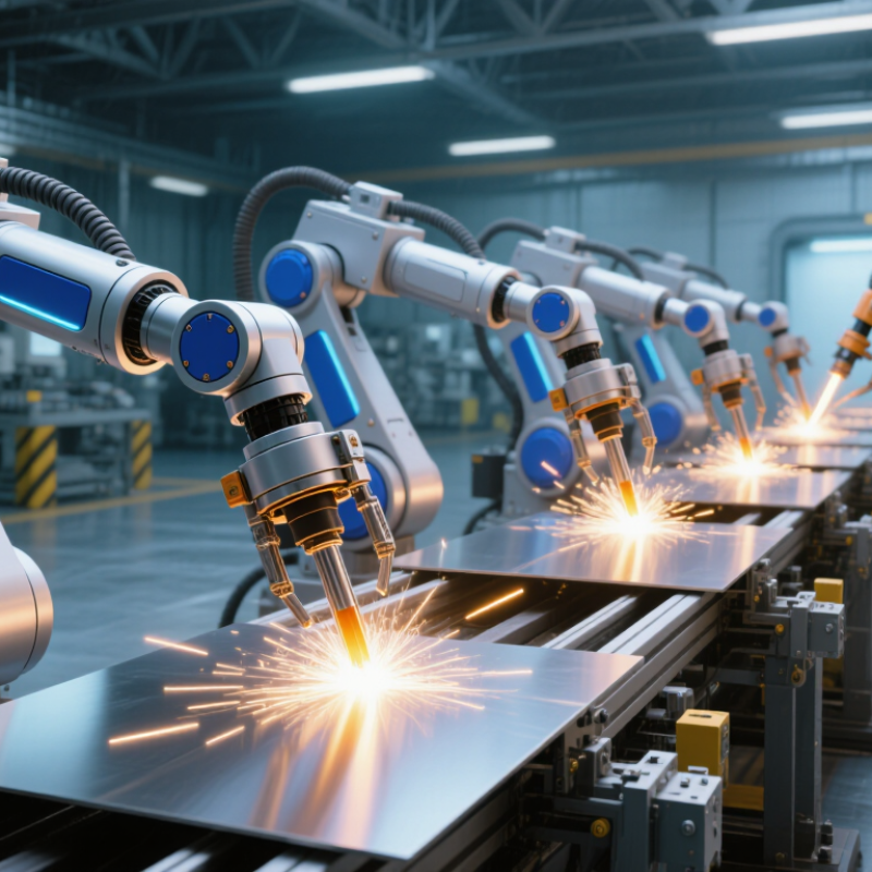
Robotic TIG welding combines a programmable robot with a controlled tungsten arc process. The tungsten electrode does not melt into the joint. Instead, an electric arc melts the base metal, while argon shielding protects the weld pool from atmospheric contamination. Filler wire can be added separately, giving operators precise control over bead shape and heat input.
The robot must maintain torch angle, arc length, travel speed, and work distance. Small changes can create visible porosity or uneven penetration. A high-frequency start helps establish the arc without touching the workpiece. Current control then manages the heat cycle, especially on thin stainless steel or aluminum. Sensors may track joint position, but sensing is not magic.
The International Federation of Robotics reported 541,302 industrial robot installations worldwide in 2023. Its World Robotics 2024 report also recorded more than four million robots operating globally. These figures show wider automation adoption, not guaranteed welding quality. The U.S. Bureau of Labor Statistics projects about 45,800 annual openings for welding-related occupations. That labor pressure encourages robotic TIG investment, but skilled supervision remains essential.
A practical cell needs stable fixturing, clean material, accurate programming, and consistent gas flow. Even a polished setup can drift. I have seen minor fixture movement change a weld profile faster than expected. Some purchasing teams focus heavily on robot payload and cycle time. They should examine arc stability, service access, documentation, and operator training more carefully.
2026 Top Robotic TIG Welding Machines for Global Buyers
Key Components That Shape Performance and Welding Quality
A robotic TIG cell is only as reliable as its weakest component. The power source must deliver stable high-frequency starts, controlled pulse timing, and low current fluctuation. These details affect arc consistency, especially on thin stainless steel or aluminum parts. The torch also matters. Precise tungsten alignment, effective cooling, and clean shielding gas flow reduce porosity and tungsten contamination.
Wire feeders require equal attention. Uneven feeding can create visible ripples and costly rework. A rigid positioner keeps the joint within the robot’s working envelope. Meanwhile, encoders and torque capacity influence repeatability during long production cycles. The International Federation of Robotics reported 541,302 industrial robots installed worldwide in 2023, with more than 4.2 million operating globally. That scale increases the demand for dependable integration, not just fast motion.
Sensors and software shape the final result. Seam tracking can correct small fixture variations, while arc monitoring helps identify drift before defects multiply. Gas flow sensors are useful, but they cannot repair poor nozzle cleaning. That is an overlooked weakness. Deloitte and The Manufacturing Institute projected 2.1 million unfilled U.S. manufacturing jobs by 2030, supporting automation investment, yet automation still needs skilled supervision. In field testing, even a well-designed cell may fail when fixtures flex, cables bend sharply, or operators skip calibration. Performance claims should therefore be checked against material thickness, duty cycle, joint access, and local electrical standards.
Key Components That Shape Performance and Welding Quality
The normalized 100-point engineering priority index highlights how major robotic TIG subsystems typically influence arc stability, shielding, positioning accuracy, heat control, and repeatable weld quality. Actual results depend on material, joint design, welding procedure, and system configuration.
In 2026, robotic TIG buyers can choose several machine types and cell configurations. The main division is between DC TIG, AC TIG, and pulsed TIG systems. DC TIG suits stainless steel, carbon steel, and many nickel alloys. AC TIG handles aluminum and magnesium with adjustable cleaning action. Pulsed TIG controls heat input through rapid current changes. Short pulses can reduce distortion and improve thin-sheet control. It also demands careful parameter testing.
For high-volume production, six-axis robotic TIG cells offer flexible torch movement and repeatable weld paths. Orbital TIG machines suit pipes, tubes, and circular joints with controlled rotation. A fixed-torch cell can reduce motion complexity for repeated assemblies. Multi-station cells allow loading at one position while welding continues elsewhere. Positioners matter greatly. They rotate workpieces for better torch angles and smoother bead placement. Poor positioning can create defects, even with a precise robot.
Configuration choices include air-cooled or water-cooled torches, automatic wire feeders, hot-wire systems, and integrated fume extraction. Touch sensing helps locate inconsistent joint edges before welding. Arc monitoring can record current, voltage, travel speed, and interruption events. Local power requirements and service access also deserve attention. No configuration is perfect. A faster cell may become difficult to maintain. Factory trials should test real materials, joint gaps, cycle times, and operator adjustments. Buyers should request sample welds, inspection records, spare-part plans, and clear programming documentation before approval.
For global buyers, comparing robotic TIG welding machines requires more than checking price and arm reach. Match the system to your actual weld geometry, materials, and production volume. A narrow torch may reach small stainless-steel joints, yet struggle around deep fixtures. Check current range, arc stability, positioner capacity, duty cycle, and repeatability. Request sample welds using similar thicknesses and joint designs. Real weld evidence matters.
Experienced buyers also examine total ownership costs. Include installation, training, shielding gas control, spare parts, software updates, and local technical support. Ask for electrical documentation and certifications suitable for the destination market. Test the programming interface before purchase. A smooth demonstration can hide difficult daily adjustments. That deserves careful questioning. Review maintenance access, cable protection, fixture changeover time, and emergency safeguards. A few minutes saved per cycle may become significant across several shifts. Still, production estimates are rarely perfect; operators often discover fixture or cleaning issues after installation.
Tips: Build a comparison sheet with measurable criteria. Score weld quality, programming time, service response, and documentation separately. Ask suppliers to explain exclusions in writing. Visit a working installation when possible. Bring an operator into the evaluation, because practical feedback can challenge engineering assumptions.
A practical comparison of common robotic TIG system configurations. Values below are indicative planning ranges, not specifications for a particular product; confirm capabilities, safety requirements, and process results with the system integrator and equipment documentation.
| System configuration | Typical robot reach | Typical repeatability | Common TIG power-source range | Best-fit applications | Key advantages | Main trade-offs | Buyer checks |
|---|---|---|---|---|---|---|---|
| Compact 6-axis industrial robot cell | Approximately 0.5–1.0 m | Often around ±0.02–0.05 mm; verify the robot’s stated test conditions | Commonly 5–250 A, depending on material, thickness, and process setup | Small stainless-steel parts, fittings, instrument components, and repeatable short seams | Small footprint; good access to intricate joints; suitable for dedicated, repeatable production | Limited working envelope; fixtures and part presentation must be carefully designed | Check torch access, cable and hose routing, fixture loading space, and whether the required seam fits within the usable reach. |
| Medium-reach 6-axis industrial robot cell | Approximately 1.2–2.0 m | Often around ±0.03–0.08 mm; actual performance varies by robot and operating conditions | Commonly 5–350 A; higher-output sources may be selected for specific applications | General fabrication, pressure-vessel subassemblies, frames, and medium-sized stainless or aluminium parts | Balances working envelope and cell size; supports a broad range of part geometries and torch orientations | Needs more floor space and guarding than a compact setup; programming and fixture design remain important | Compare reach at the actual torch angle, payload including torch and cables, positioner integration, and service access. |
| Long-reach or track-mounted robot cell | Robot reach commonly about 1.5–3.0 m; a linear track can extend the work envelope | Robot repeatability is model-dependent; track accuracy and calibration also affect torch positioning | Commonly 5–350 A, selected for the joint and material rather than the robot reach | Large assemblies, long seams, and parts that are difficult to reposition | Can cover a large work area; may reduce repeated part handling and the number of separate stations | Higher system complexity; track alignment, guarding, cable management, and calibration need attention | Assess total travel, usable reach at the far ends, track positioning accuracy, foundation needs, and maintenance access. |
| Collaborative-arm TIG station | Often approximately 0.7–1.3 m, depending on the arm | Commonly around ±0.05–0.1 mm; confirm the specific arm’s published value | Typically paired with a compatible TIG source, often within roughly 5–250 A | Low-volume production, frequent changeovers, and tasks where an operator works near the station | Can be relatively straightforward to redeploy; some setups offer hand-guided programming | Collaborative status does not make arc welding inherently safe without risk assessment and suitable protective measures; speed, reach, and payload may be limited | Review the complete risk assessment, welding-arc protection, fume control, torch and cable load, and the validated operating mode. |
| Robot with rotary positioner or coordinated axes | Depends on the robot; positioner capacity and axis travel define the overall work envelope | Depends on robot, positioner, calibration, and coordinated-motion setup | Commonly 5–350 A; pulsed TIG and other process options depend on the selected power source | Circumferential joints, pipe sections, and parts that benefit from maintaining a consistent welding position | Can improve torch orientation and joint access; coordinated movement may help maintain a more consistent process path | Requires reliable synchronization, part clamping, axis calibration, and appropriate programming expertise | Confirm workpiece mass and inertia, positioner accuracy, axis coordination, cable clearance, and the required weld-position strategy. |
Selection note: TIG process settings, achievable travel speed, weld quality, and cycle time depend on joint design, material and thickness, filler-wire strategy, part fit-up, shielding-gas arrangement, and operator or integrator process development. Request a representative sample weld and a documented acceptance test before purchase.
Installation begins with the floor, not the robot. A rigid, level foundation limits torch vibration and improves arc consistency. According to the IFR World Robotics 2024 report, 541,302 industrial robots were installed worldwide in 2023. That growth makes local commissioning skills increasingly important. Buyers should verify power frequency, shielding-gas quality, grounding, and spare-part access before shipment. European, North American, and Asian facilities may require different electrical documentation and risk assessments. A translation error can become a production hazard.
Safety needs physical design and disciplined habits. ISO 10218-1 and ISO/TS 15066 support risk-based safeguarding, protective stops, and validated operating zones. Welding cells need interlocked doors, light curtains, fume extraction, and tested emergency stops. OSHA’s welding guidance also emphasizes ventilation and protection from radiation, sparks, and electric shock. Do not trust software limits alone. They can fail.
Maintenance is less glamorous, but more decisive. Record torch alignment, liner wear, gas flow, cable condition, and TCP accuracy after every service interval. The World Robotics report shows robot adoption accelerating, yet many smaller plants still lack trained technicians. That gap is real. A monthly inspection may look sufficient, but dusty workshops often need weekly cleaning. Operators should photograph abnormal weld spatter and compare bead profiles. Data helps, though imperfect records still mislead. Calibration schedules must follow actual duty cycles, not optimistic assumptions.
© 1999-2025 The Lincoln Electric Company