
What Are the Top Types of Robotic Welding in 2026?

In 2026, robotic welding is no longer limited to high-volume automotive lines. Manufacturers also use automated welding cells for repeatable work on machinery, metal furniture, and fabricated components. The International Federation of Robotics’ World Robotics 2024 report recorded 541,302 industrial robot installations worldwide in 2023, with 4,281,585 robots operating across industries. These figures describe all industrial robots, not welding systems alone. They show the scale of automation, but should not be mistaken for a welding-specific forecast. A robot count is not a process ranking. That distinction matters.

The main robotic welding types considered here are arc welding, resistance spot welding, laser welding, and friction stir welding. Collaborative robots are also discussed, though they are a deployment approach rather than a welding process. Each option solves a different production problem: an arc torch follows a seam, while spot-welding electrodes clamp overlapping panels. Laser systems can produce narrow, precise welds, but require careful joint preparation and process control. Friction stir welding joins materials through pressure and friction, making it relevant for certain applications where conventional fusion welding is unsuitable. No single process wins everywhere. A small fixture change can affect access, cycle time, and weld consistency. It is easy to overlook that detail. This guide compares the practical strengths, limitations, and typical uses of each type, while noting where the available industry data does—and does not—support broad claims.
What Are the Top Types of Robotic Welding in 2026?

Define the 2026 Landscape: IFR Counted 4.28 Million Operating Robots in 2023

What Are the Top Types of Robotic Welding in 2026?

The global robot base is expanding. The International Federation of Robotics reported 4,281,585 industrial robots operating worldwide in 2023, with 541,302 new installations that year (World Robotics 2024). These figures describe all industrial robots, not welding systems alone. Still, they show the scale of automation available to manufacturers. The distinction matters.

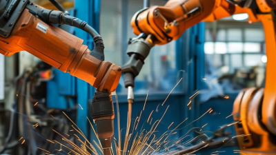
In welding cells, arc welding is widely used for repeatable seams on frames and fabricated parts. Resistance spot welding suits fast, repeated joints, especially in high-volume production. Laser welding can deliver narrow, precise seams, but needs careful fit-up and process control. These are practical categories, not a universal ranking. The right method depends on material, joint design, production volume, and inspection needs.

Tips: Match the process to the part before choosing a robot. Check sample welds, cycle time, and fixture access. IFR’s total robot count is useful context, but it cannot predict demand for any single welding type. That gap is easy to overlook. A robot may repeat a poor setup perfectly, so operators still need to verify the first pieces and revisit settings when parts change.

Arc-Welding Robots: Apply AWS D1.1 Requirements to GMAW Cell Design

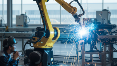
Arc-welding robots are widely used for repeatable GMAW on structural steel, especially where joints and access remain consistent. The International Federation of Robotics reported 541,302 industrial robot installations worldwide in 2023, with 4.28 million operating robots. These figures cover all industrial robots, not welding systems alone, but show the growing automation base. A robot can trace a seam. It cannot decide whether the seam meets code.

For a GMAW cell designed around AWS D1.1, begin with the applicable code edition, base-metal group, joint details, welding position, and thickness range. Confirm that the welding procedure specification is prequalified only when every code condition is satisfied; otherwise, procedure qualification may be required. Document the wire, shielding gas, transfer mode, voltage, travel speed, preheat, and interpass temperature within permitted limits. Then plan inspection access and retain traceable production records. A torch can repeat a poor fit-up perfectly. That is an uncomfortable, practical lesson: robot repeatability does not replace fit-up control, qualified procedures, or inspection.

Tips: Run coupons using real production gaps and fixtures. Check starts, stops, and corners, where lack of fusion can hide. Record parameter changes, and review them against the approved procedure before production.

Resistance Spot-Welding Robots: Examine High-Volume Automotive Applications

What Are the Top Types of Robotic Welding in 2026?

Resistance spot-welding robots suit high-volume automotive lines, where steel panels meet at repeatable points. A robot positions the gun, clamps the sheets, and sends a controlled electrical current through them. The resulting heat forms a weld nugget. Cycle time matters. Small errors spread. Poor part fit or worn electrode tips can weaken consistency across a long production run.

A dependable cell needs more than a fast robot. Engineers match gun reach, electrode force, weld schedules, and fixtures to the body design. Sensors can track current and force, while routine inspections catch tip wear before defects multiply. Operators still matter: they verify setup, review alarms, and notice changes that automated checks may miss. Even a carefully tuned line can behave unevenly when panel gaps shift. That deserves attention, not an assumption that automation fixes every variation.

Tips: Keep electrode tips clean and correctly dressed. Check sample welds after setup changes, and log recurring faults. Small adjustments can help, but record them; otherwise, yesterday’s fix may become tomorrow’s mystery.

Laser and Hybrid Welding Robots: Compare ISO 13919-1 Weld Quality Levels

In 2026, comparing laser and hybrid welding robots means looking beyond speed. ISO 13919-1 sets quality levels for imperfections in laser-beam welded joints made from specified materials, including steel, nickel, and titanium alloys. Level B is the most demanding, C is intermediate, and D allows more imperfections. These levels describe weld quality requirements, not a ranking of robot types.

A laser robot concentrates energy into a narrow seam. That can produce a slim weld, but joint gaps and alignment errors may matter greatly. Hybrid systems combine laser energy with an arc, often making them more tolerant of fit-up variation. They also bring extra process variables. For hybrid welds, confirm that the chosen standard and acceptance criteria fit the joint and application; do not assume every ISO 13919-1 requirement transfers unchanged.

Consider a thick steel panel with a small root gap. A laser-only cell may need tighter fixturing, while a hybrid setup may bridge the gap more readily. Either process can miss the specified quality level if parameters drift or inspection is inadequate. Reality is less tidy. Select B, C, or D from design needs and documented risk, then verify welds using suitable inspection methods. The toughest level is not automatically the best choice for every component.

Laser and Hybrid Welding: ISO Weld Quality Levels

A qualitative comparison of the stringency of ISO 13919-1 quality levels.

Level B is the most stringent, followed by C and D. The 3–1 scale is an ordinal visual aid, not a standard measurement or acceptance limit; permitted imperfection values depend on the imperfection type and other applicable requirements. ISO 13919-1 covers electron- and laser-beam welds. For laser-arc hybrid welds, confirm the governing standard and acceptance criteria in the project specification.

Friction-Stir Welding Robots: Assess TWI’s Solid-State Process for Aluminum

Friction-stir welding robots join aluminum without melting it. A rotating tool presses into the seam, stirring softened metal as the robot travels along the joint. No melting occurs. This solid-state process can reduce porosity and distortion compared with fusion welding, especially on long, straight seams. It is worth assessing for battery trays, vehicle structures, and other aluminum assemblies where consistent joints matter. Yet results depend on alloy, thickness, tool design, and carefully controlled force.

A robot must hold the tool at a steady angle and maintain pressure despite small fixture variations. That is harder than it sounds. The process can demand stiff equipment, secure clamping, and access for a bulky tool head. Start and stop points also need attention; exit holes may require a run-off tab or another design solution. It is not a universal replacement for arc welding. A practical trial should compare joint strength, surface finish, cycle time, and tool wear using the actual part geometry.

Tips: Start with flat coupons made from the production alloy and thickness. Record tool force, speed, and joint temperature, then inspect cross-sections for bonding defects. Leave room for refinement: fixture movement can spoil an otherwise promising setup.

What Are the Top Types of Robotic Welding in 2026? — Friction-Stir Welding Robots: Process Assessment for Aluminum
Assessment Dimension Friction-Stir Welding (FSW) Facts Robotic Application Assessment
How the process works A rotating, non-consumable tool with a shoulder and pin moves along the joint. Frictional heating and severe plastic deformation soften and mix the material without melting it. Robot motion must maintain the tool’s position, orientation, travel path, and contact conditions throughout the weld.
Why it is called solid-state The material is joined below its melting point, so the process avoids the liquid weld pool used in conventional fusion welding. This can reduce problems associated with solidification, though it does not eliminate every weld defect or quality-control requirement.
Aluminum suitability FSW is used for many aluminum alloys and is particularly relevant to plate, sheet, and extruded sections that can be securely fixtured. Alloy, temper, thickness, tool design, and joint setup affect the usable process window; each application requires qualification.
Common joint configurations Butt and lap joints are established FSW configurations. Other geometries may be possible with suitable tooling and access. Robot reach and tool clearance must be checked against the component geometry, clamping arrangement, and weld path.
Filler material and shielding gas The process typically uses neither filler wire nor shielding gas because it does not create a molten weld pool. Removing these consumables can simplify material handling, but the tool itself is a wear component and must be monitored.
Potential weld benefits Compared with fusion welding, FSW can reduce solidification-related defects such as hot cracking and can produce low-distortion joints in suitable applications. Actual joint quality depends on process parameters, fit-up, restraint, tool condition, and inspection; benefits should be confirmed by testing.
Equipment and structural demands The tool applies substantial axial and traverse forces while rotating and moving along the seam. A robotic cell needs adequate stiffness, force capacity, fixture strength, and control. Robot payload alone does not establish process suitability.
Process control Important variables include tool rotation speed, travel speed, axial force or position, tool tilt, plunge depth, and material condition. Force or position feedback and consistent path control can help manage variation. Parameter values are application-specific rather than universal.
Typical limitations Potential challenges include demanding clamping, tool wear, exit-hole management, restricted access, and sensitivity to joint fit-up and process setup. Cell design should account for tool entry and exit, backing support, part restraint, maintenance access, and inspection needs.
Best-fit use cases FSW is worth evaluating for repeatable aluminum joints where solid-state joining, low consumable use, or reduced fusion-related defects are important. It is most attractive when parts can be fixtured consistently and the production volume and joint design justify dedicated tooling and process qualification.